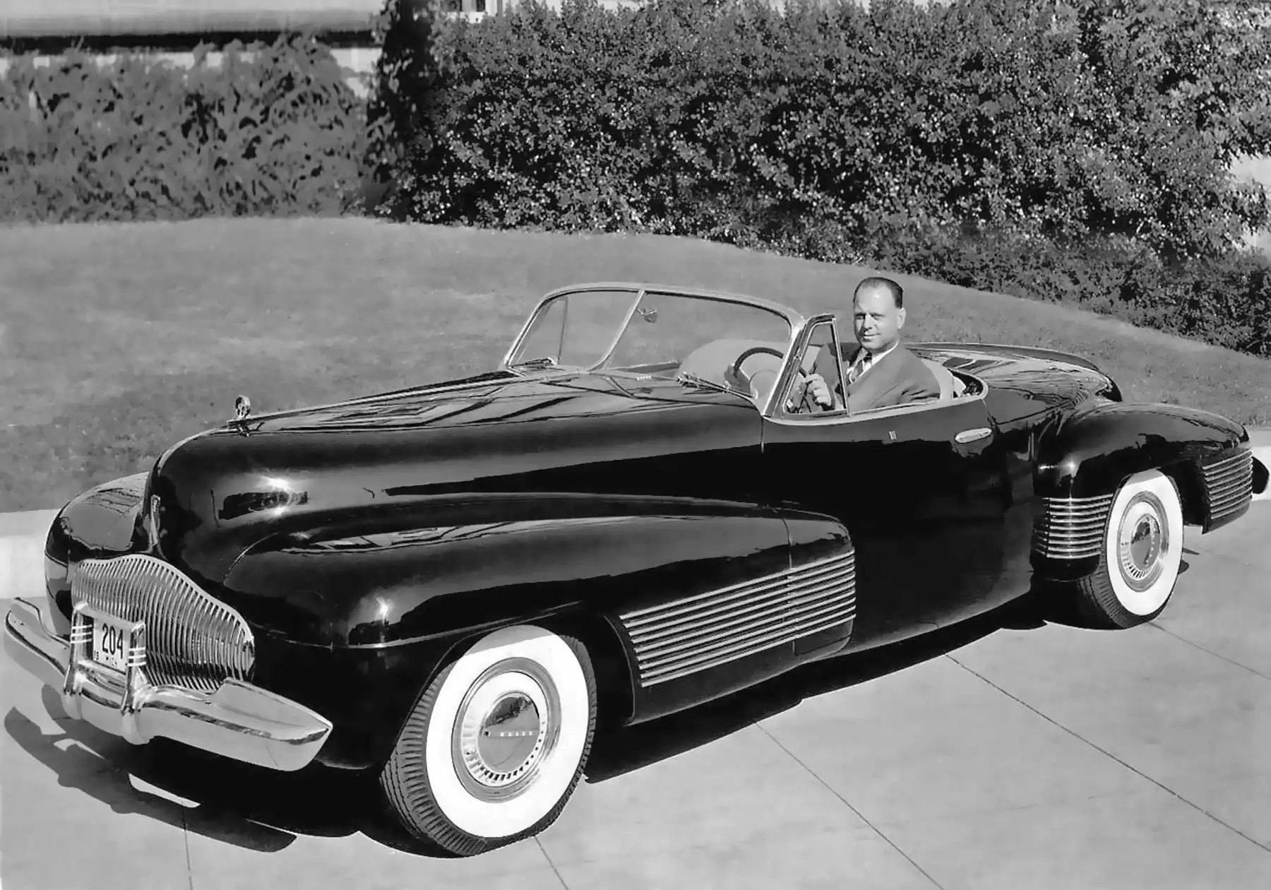
1939 Buick Y Job. Harley Earl. The first Concept Car. Image credit: GM Photographic Image
Since the invention of the automobile, vehicle manufacturers needed to study different concepts of future vehicle designs. After reviewing different designs, final approval is made for the upcoming year’s production or new design cycle.
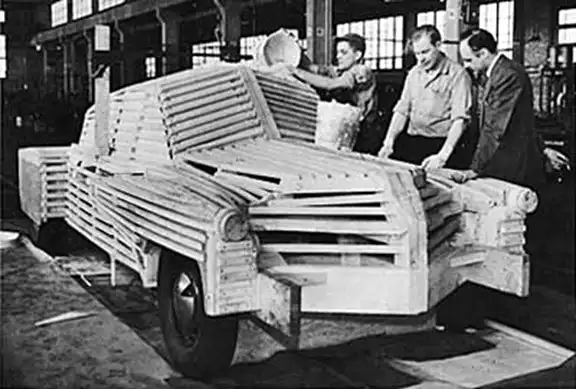
The earliest days of car design were done mostly as 2D drawings. Automobile design was a low priority because it was limited by engineering needs, metal forming technology, and cost concerns. Furthermore, demand outstripped supply and consumers didn’t prioritize design as a purchase criteria. Therefore, cars simply looked alike, lacked variety, and didn’t change design frequently. As car designs were updated more frequently, wood scale models or larger wood frame models covered in plaster were used.
In the late 1920s and 1930s, legendary GM designer Harley Earl is credited with groundbreaking achievements that ultimately lead to the invention of the claymill. These include transforming GM’s “Art and Color Section” to a first-of-its-kind car design studio we would recognize today. At GM, Harley pioneered product differentiation via compelling industrial design.
Harley created the first full size 3D models for all new car designs as standard practice. He created the first concept car, the Buick “Y Job”. He also pioneered the concept of annual updates or “dynamic obsolescence” to drive consumer demand.
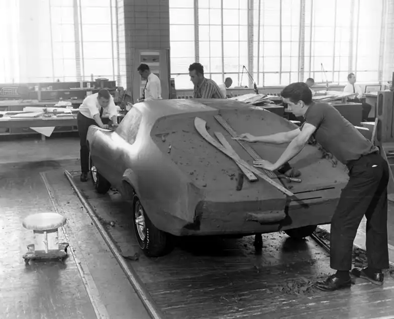
Helping weave all of these breakthroughs together, Harley Earl introduced clay as a medium for car design concepts. Once clay became established as the medium for car models, a wide variety of techniques and tools were used to develop vehicle shapes in clay.
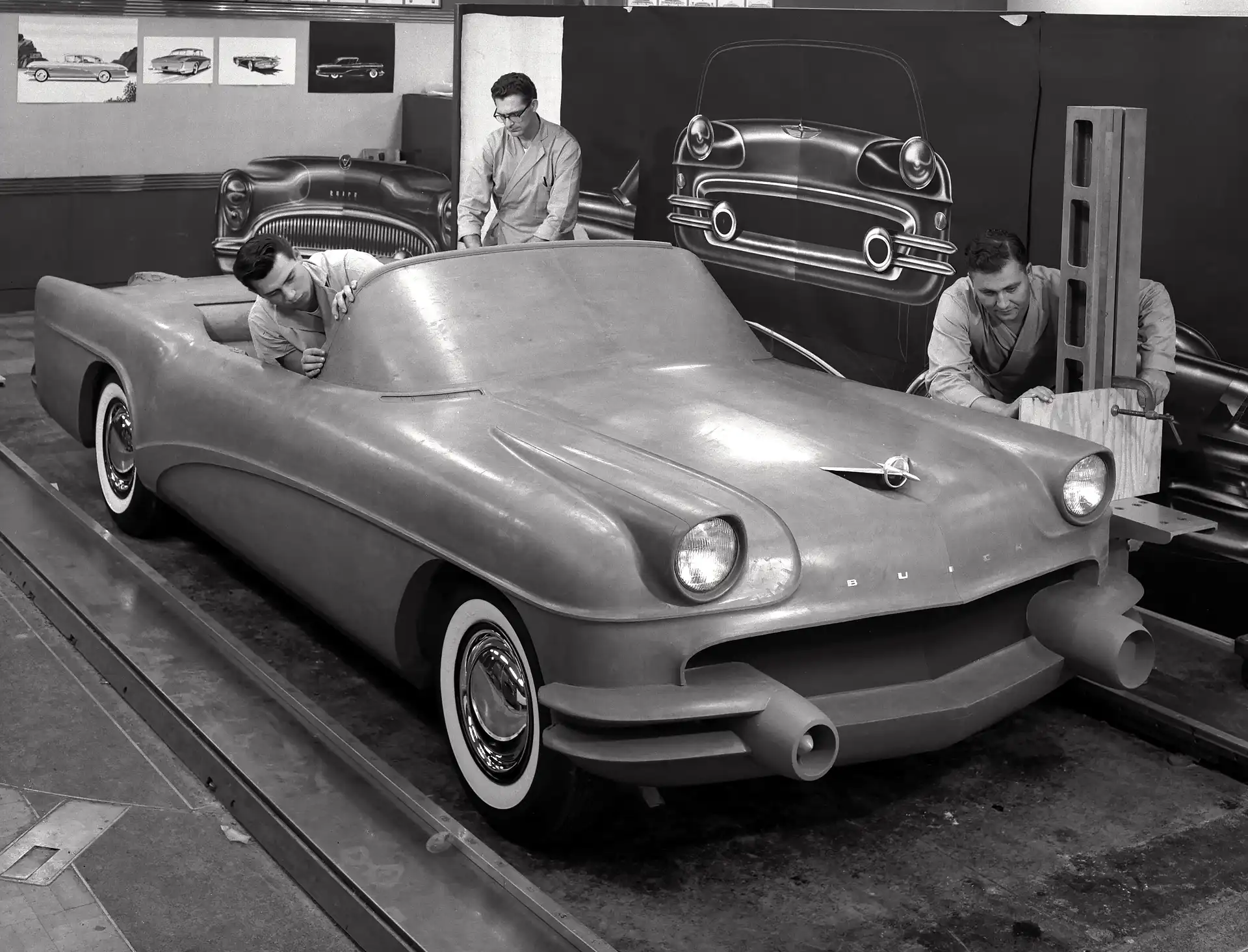
For stability, clay models were constructed on level floor plates constructed of steel or granite. Some design center buildings could not support the weight, so special fixtures were made to align the model with rails.
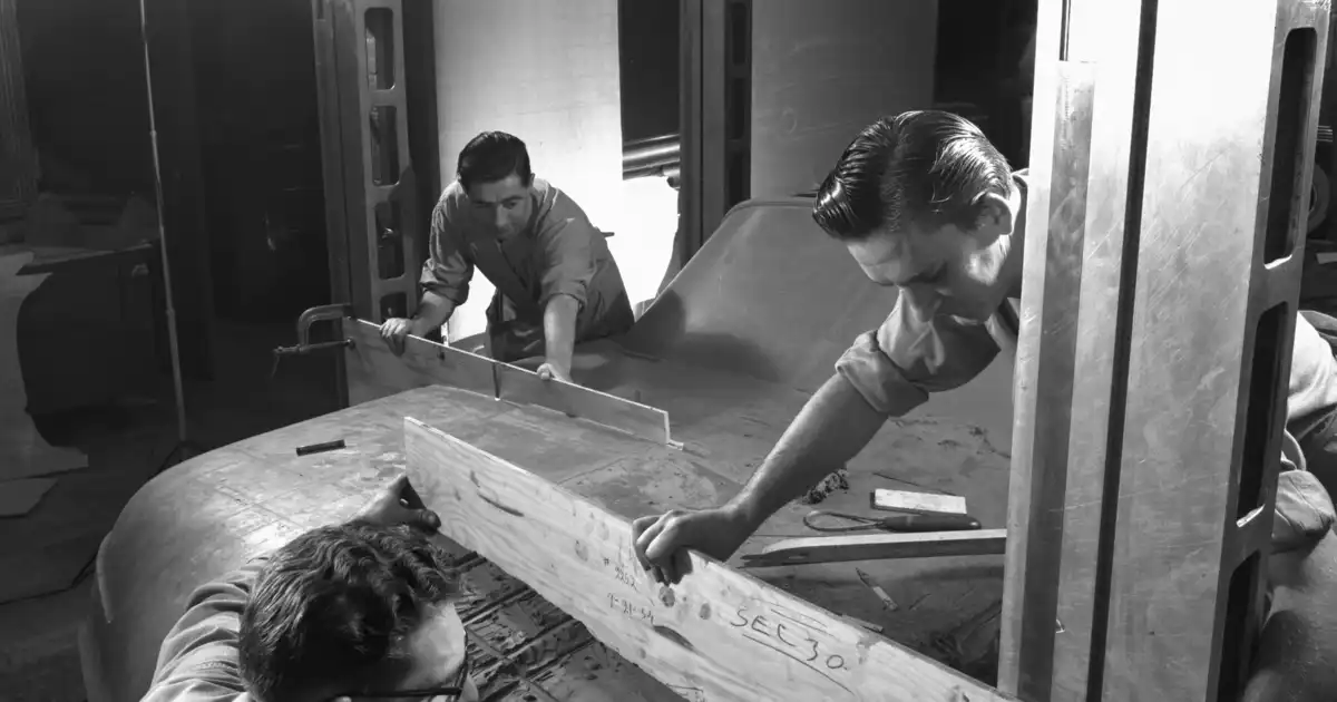
Alongside the rails, sculptors used height gauges that measured points on the model so features could be transferred to the opposite side of the model. Sculptors also used wooden templates called ‘sweeps’ to reproduce curves and radii from on side of the model to the opposite side or a different model.
Height gauges became larger and were optimized for clay modelling with the addition of scales and locking vertical platforms. Therefore, a parallel gauge could span across the model allowing the sculptors to balance the shape of the model more easily on both sides.
In the 1960’s this idea went further. Complex mechanical bridge devices allowed the user to automatically transfer points from one side of the model to the other. A stylus moved on one side would be mirrored on the opposite side. Eventually these bridges included digital feedback of the X, Y and Z axis position of the stylus so that point could be accurately verified and recorded.
Use of a wooden template. GM, 1946. Image credit: GM Photographic Image
Ford, 1950. Image credit: Unknown.
1954 Buick Studio Wildcat III, using height gauges. Image credit: GM Photographic Image
Height guages and wooden drag. Image credit: GM Photographic Image
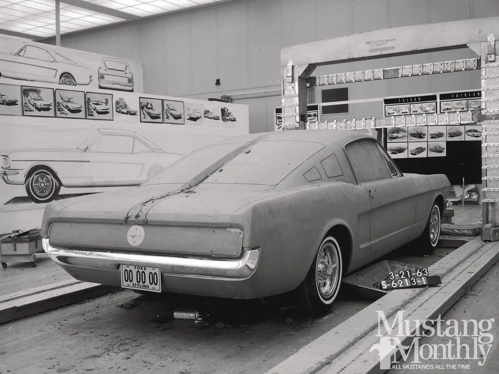
Ford Mustang, mechanical bridge device. Image credit: Mustang Monthly.
Using sweeps. Image credit: Unknown.
Example of a large, bulky CNC machine used to mill a scale model. Image credit: Unknown
Clip of the history of the Claymill from Autoline After Hours episode 605. To view the full episode discussing the history of the Claymill, click here.
Parallel paths of development occurred when some design studios adopted manual 3-axis layout machines and then electronically controlled and positioned CMM (coordinate measuring machines). The CMM created points that were drilled into the surface accurately. Then, wireframe lines allowed sculptors to scrape and remove the excess clay using sweeps to arrive at the approximate desired surface.
A separate parallel path of development used very large CNC machines to mill clay models. Typically, automobile companies or their tooling suppliers would have large 3 and 5 axis CNC machines for pattern and tool making. In some cases, those machines would mill clay models from CNC data for design studios. This was difficult because clay models were fragile, would not travel well, and the clay chips from milling would damage CNC machines designed for milling metal or wood.
Some large car companies added these heavy CNC machines to a milling room located nearby their main design studio. TARUS continues to supply these larger gantry and horizontal arm 5 axis machines to design studios and design model milling suppliers around the world. These machines mill clay, dense foam, and polyurethane for design and surface verification models.
In the 1970s and 1980s, Detroit was the epicenter of design studio innovation. General Motors was the leader, experimenting with many of these processes as they became practical. At one point in the early 1980’s GM experimented with both a CMM equipped with drill motor to drill target holes in the models and attempted to develop a prototype CNC clay milling machine.
TARUS CNC machines and CMM were already in use at most of the GM North America tooling and pattern facilities including Chevrolet and Fisher Body which were in the Warren, Michigan GM Tech Center campus next to the GM Design Center.
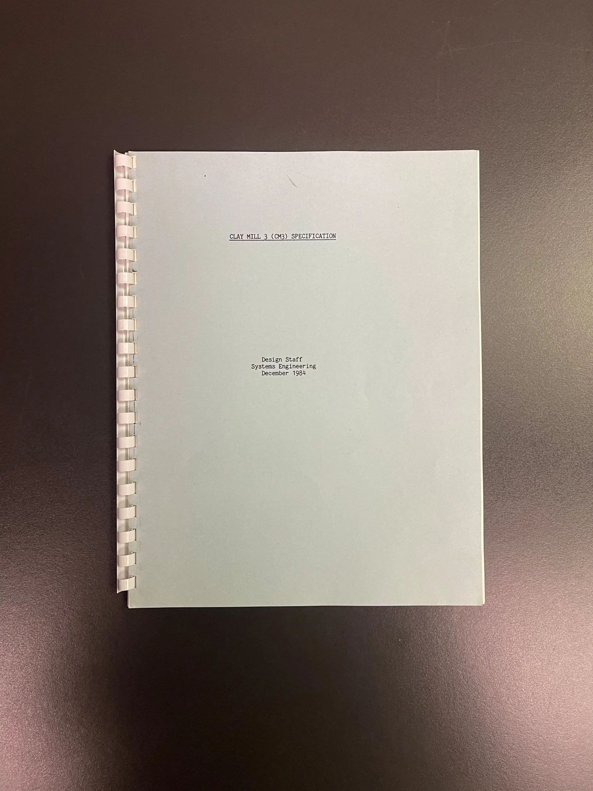
The Process Development Team at GM Design knew TARUS and approached TARUS to discuss both a 2D Digitizing Table to convert 2D drawings to digital wireframe files for their CAD/CAM process, and to help complete GM’s internally built prototype CNC Claymill which they were struggling with.
TARUS Founder, Douglas J Greig declined to complete the GM prototype but agreed to quickly build a purpose-built portable CNC clay milling machine.
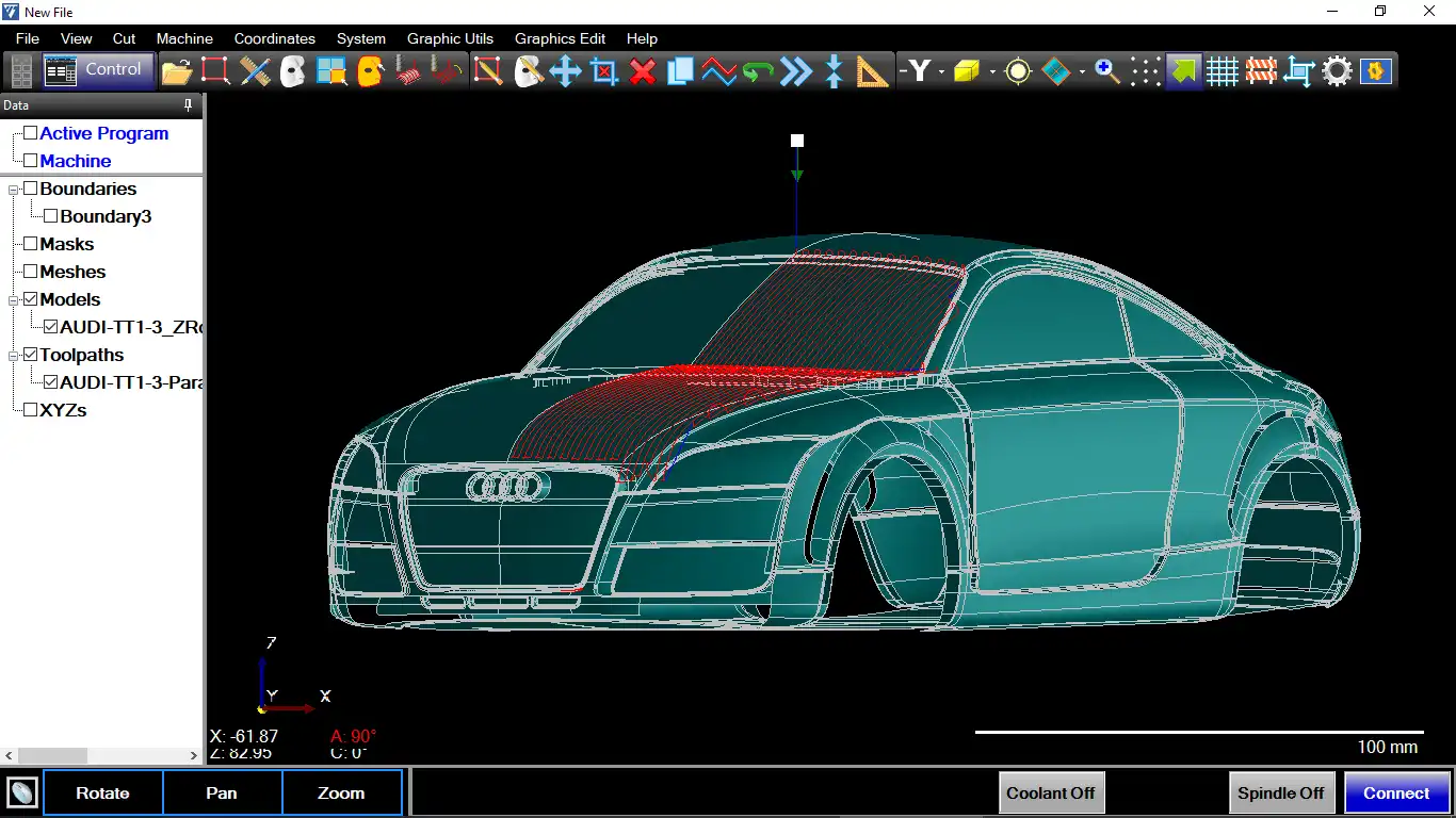
Doug’s decision to fully develop the first true purpose-built portable clay milling machine was possible due to TARUS success in building traditional large CNC machines, and by the fact that TARUS also developed its own proprietary CNC with full graphical user interface (GUI).
The TARUS GUI could accept the wireframe and math data from the carmakers’ CAD systems as well as TARUS CNC and CMM software. This enabled the measuring probe to measure the model, alignment, and origin point presetting that was needed for a portable machine to mill a full sized clay model.
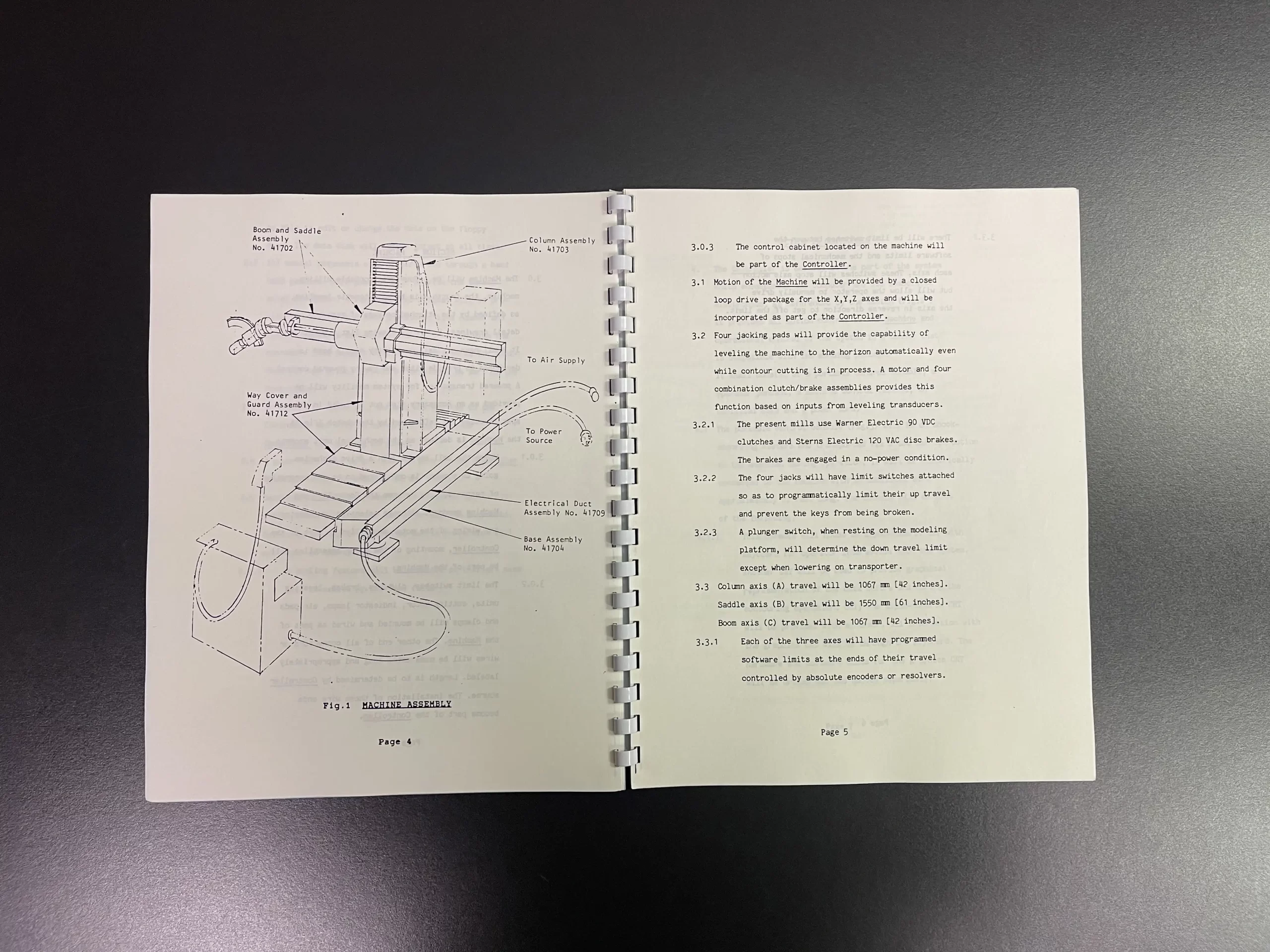
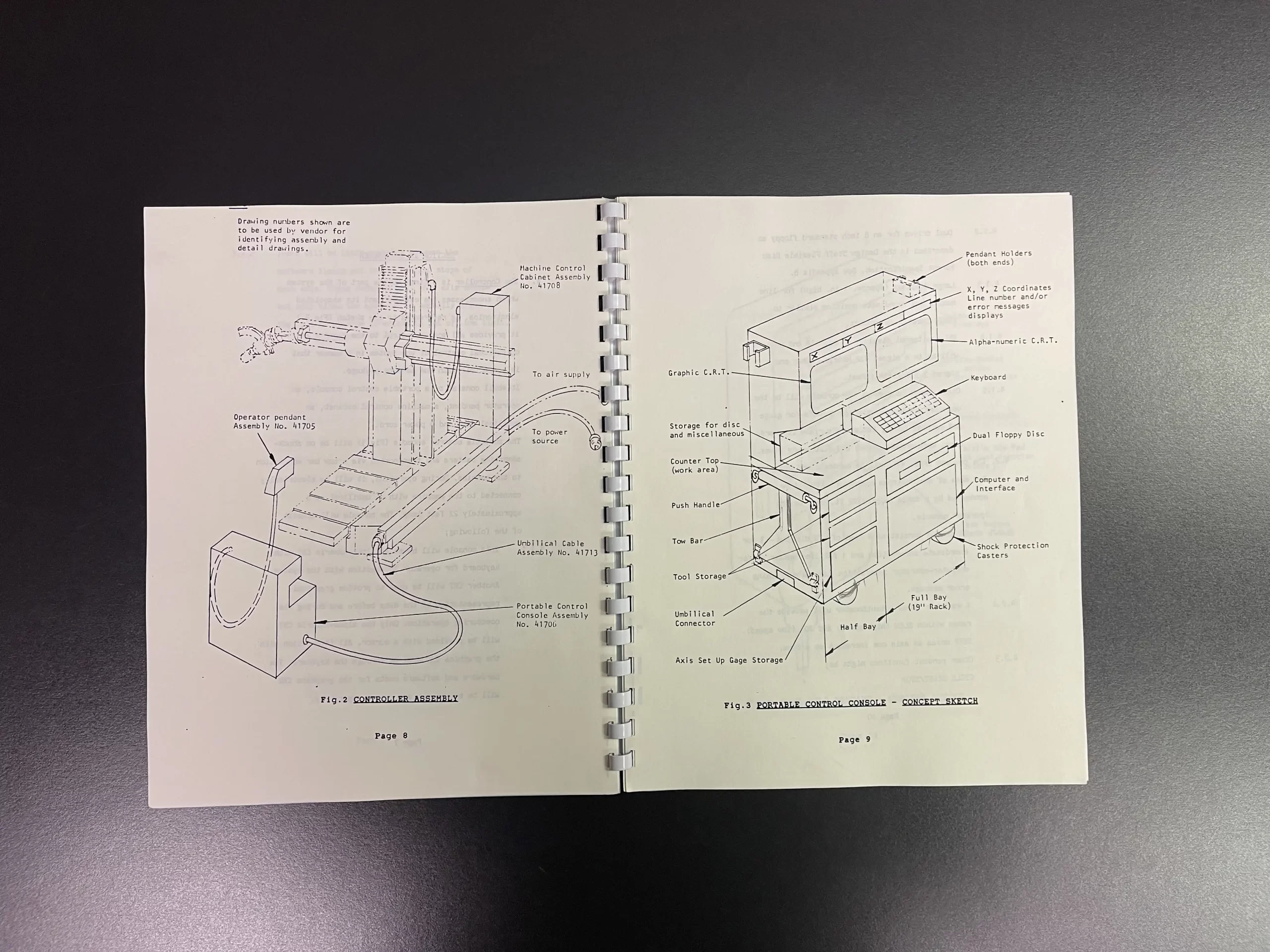
Original Claymill Specification from GM - 1984. Image credit: TARUS Archives, George Cook
Original Claymill Specification from GM - 1984. Image credit: TARUS Archives, George Cook
Original Claymill Specification from GM - 1984. Image credit: TARUS Archives, George Cook
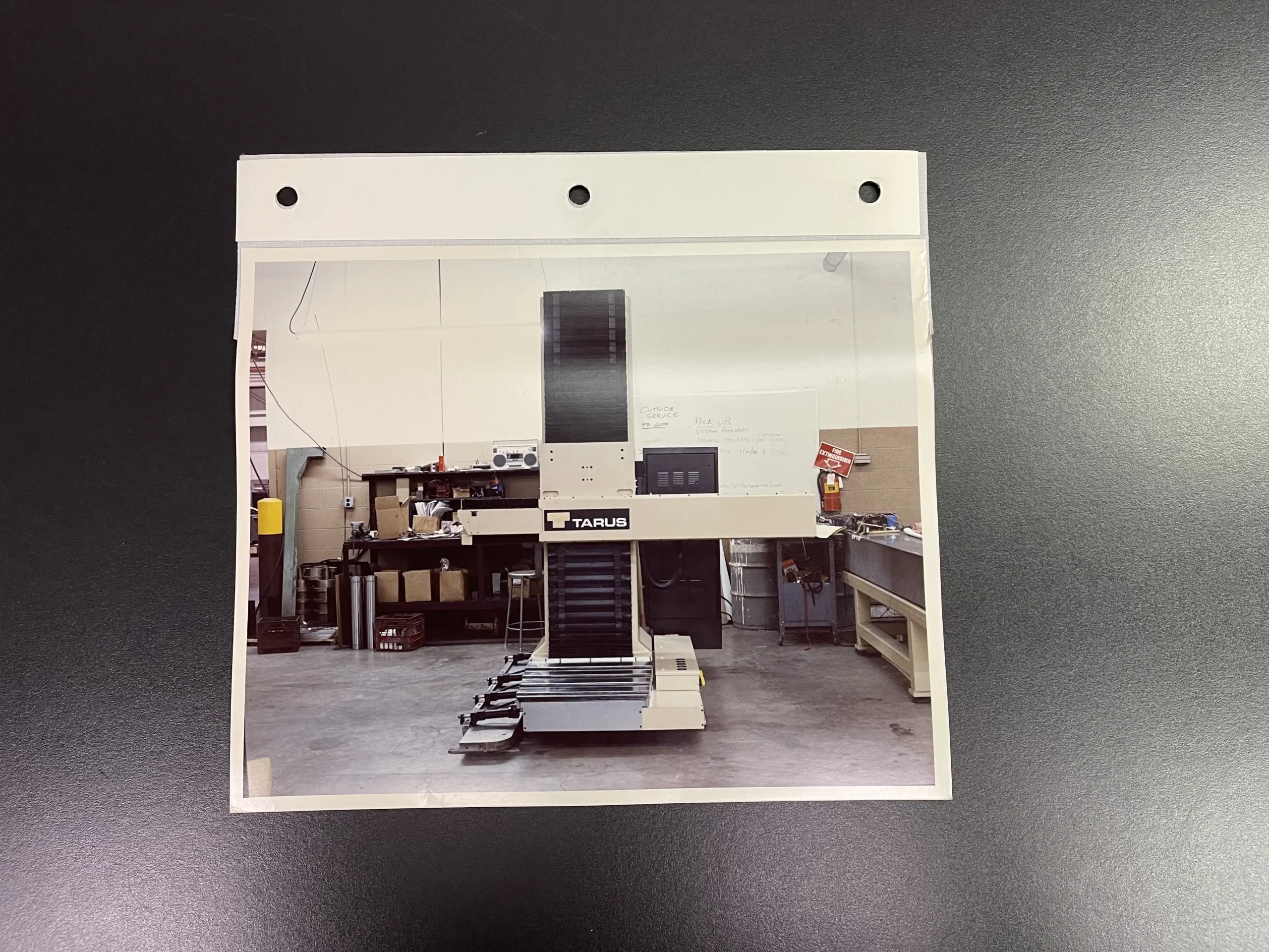
The world's first purpose-built Claymill. Image credit: Alex Khatri, TARUS Archives, George Cook
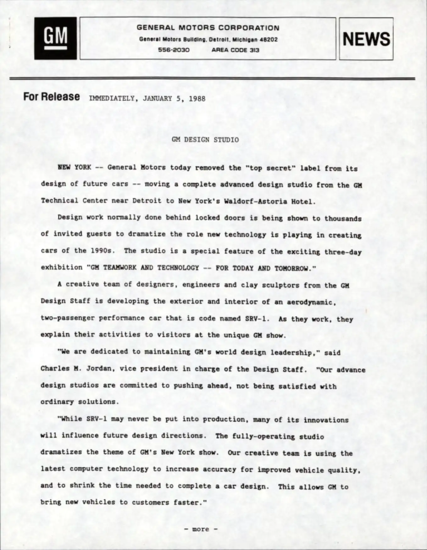
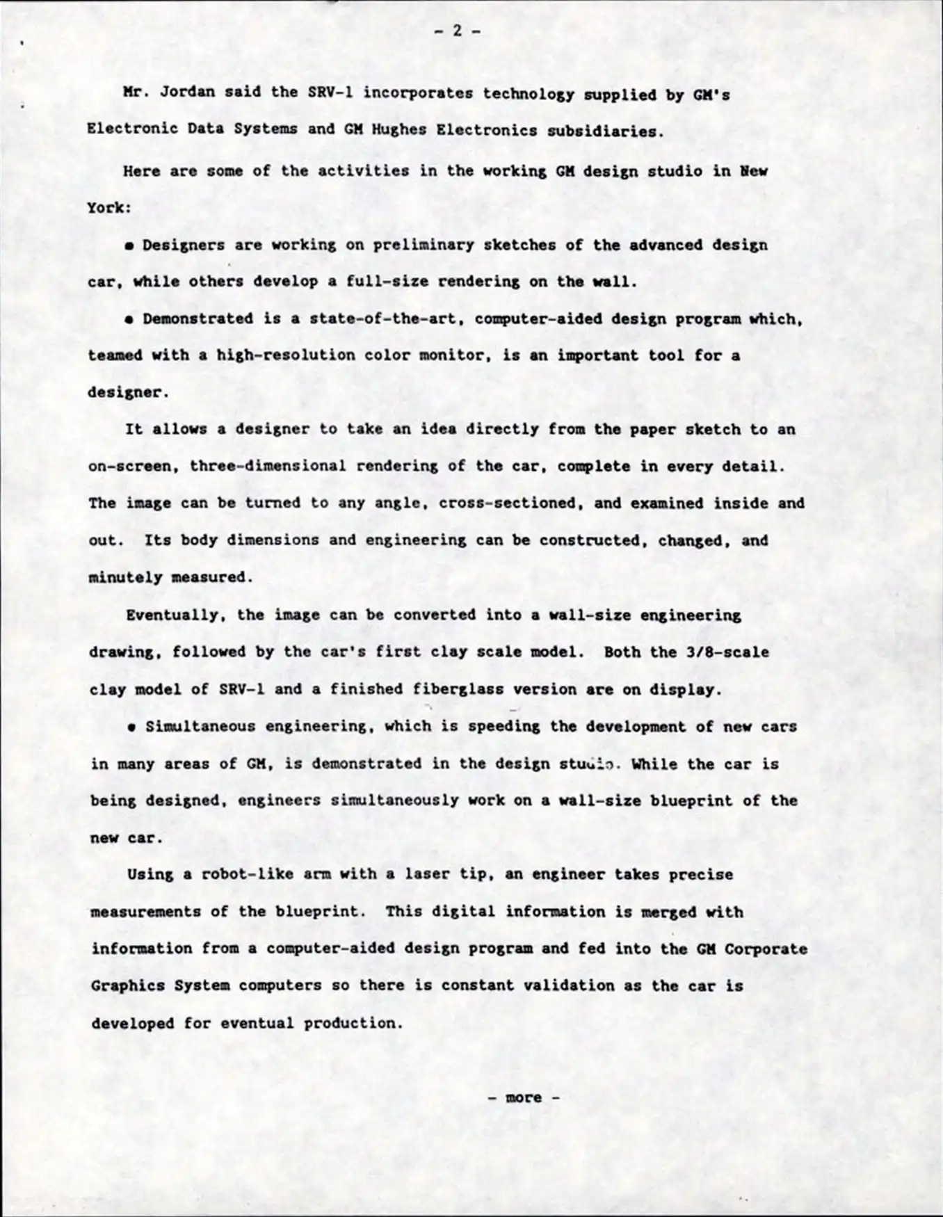
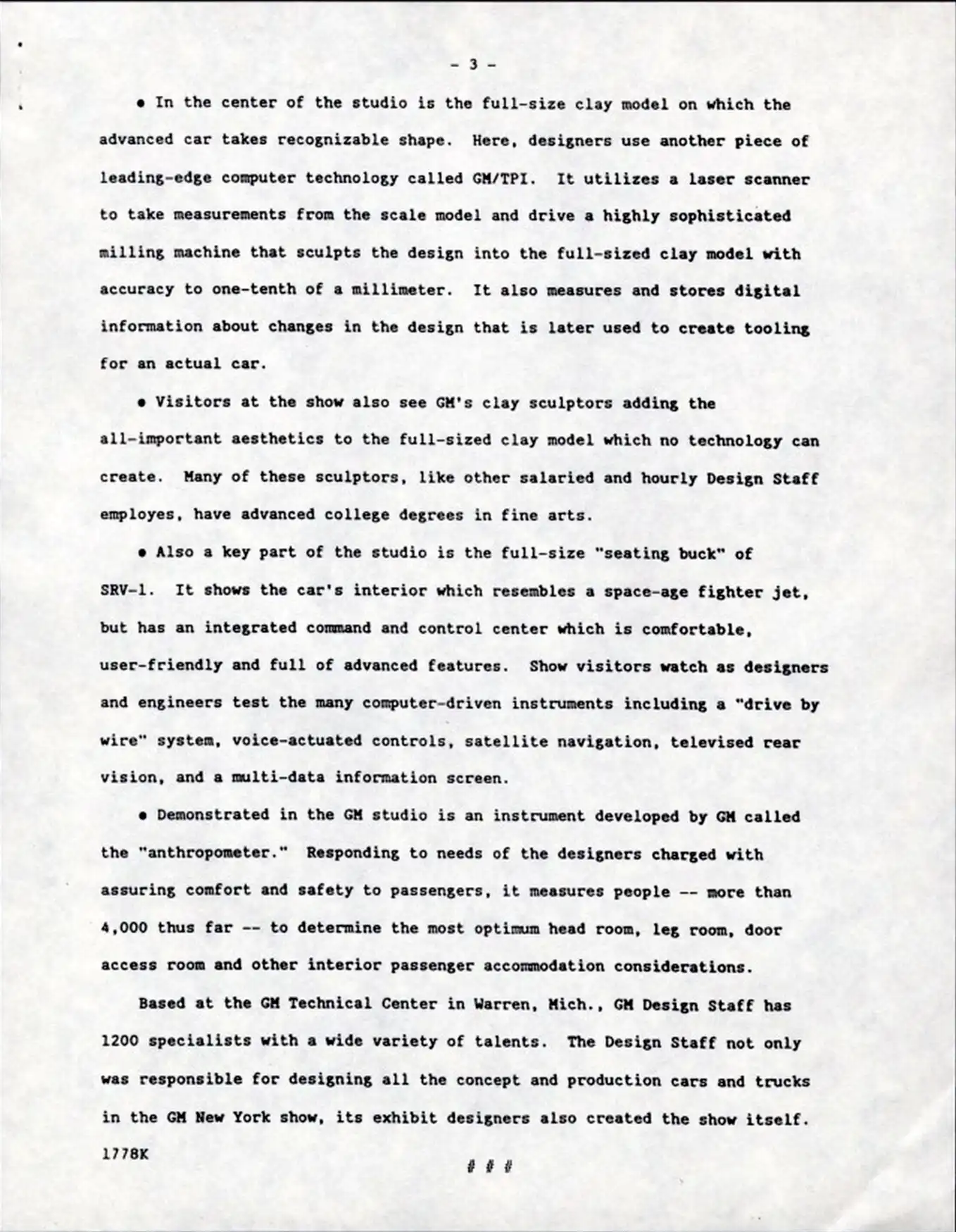
1988 GM Press Release mentioning the TARUS Claymill
1988 GM Press Release mentioning the TARUS Claymill
1988 GM Press Release mentioning the TARUS Claymill. Note: "TPI" stands for TARUS Products, Inc.
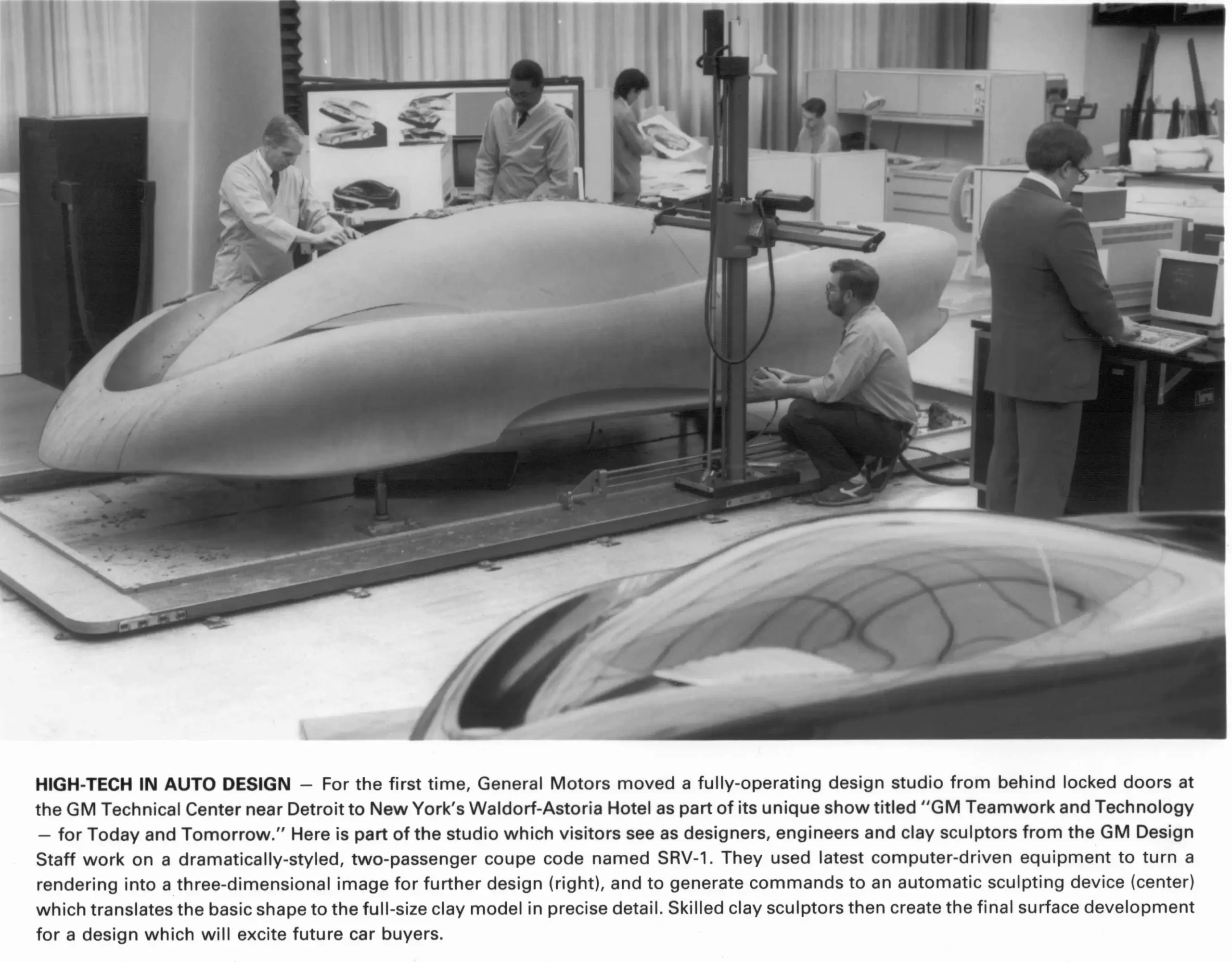
1988 GM. Pictured: Ron Parrot at TARUS Control Desk. Frank Heinzman (kneeling). Julius Dixon (standing). The original Claymill is pictured to the upper left. Image credit: GM Photographic Image
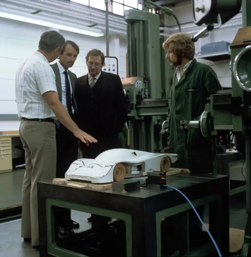
1990 Ford/Pioneer Engineering. Image credit: Alex Khatri
Besides Doug’s machine design engineering skills, TARUS had (and still has) a vertically integrated machine manufacturing operation including the machine structure fabrication, weld, CNC machining, paint, control panel wiring, machine assembly, software department, service department, and even a lab certified metrology/machine calibration department.
This vertically integrated approach allowed TARUS to quickly innovate and offer superior solutions.
This first TARUS Claymill was installed at GM in early 1986, followed rapidly by 3 more. Word spread quickly about around Detroit. Early TARUS customers included Ford, Chrysler, Cars & Concepts, Modern Engineering, Pioneer Engineering, ASC, and Creative Engineering.
Within a 2 year period from the creation of the Claymill, they all purchased TARUS Claymilling machines. GM would eventually go on to purchase over 250 machines for their various design studios in the USA, Brazil, Australia, Korea, Japan, and China.
The TARUS name quickly became synonymous in the industry with clay modeling. Generations of automotive sculptors referred to clay milling CNC machines simply as a ‘TARUS’ or ‘Claymill’.
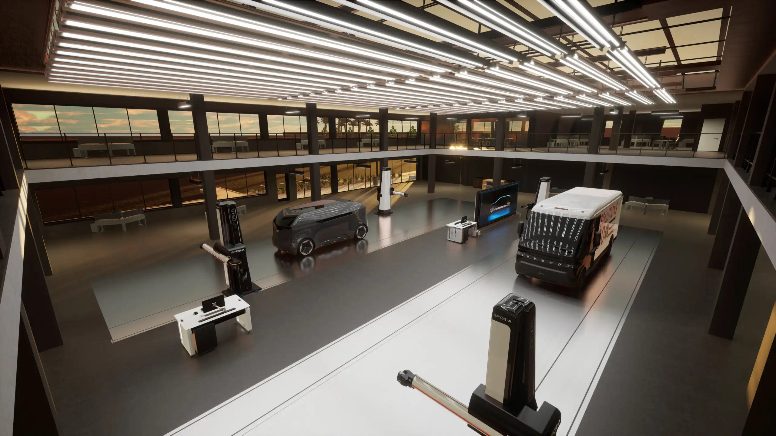
TARUS’ newest 5 Axis CNC machines are the LCMT which is a lighter, quieter machine with full 5 axis capability, as well as the CM5P (Portable) and CM5R (Rail Type) which are modern descendants of the original TARUS Claymill.
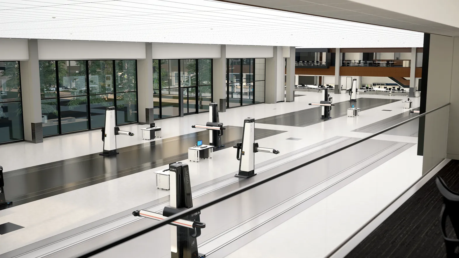
Today, GM’s massive new Design Studio in the GM Warren Tech Center is being outfitted with 38 of the new LCMT Claymill towers and nearly 1 kilometer of floor mounted rails for the machines to travel on.
TARUS remains the world leader in claymilling equipment and solutions with machines located in practically every country where transportation design studios exist.
With a history of software innovation, the TARUS user interface (UI) for Claymilling machines was specifically designed with sculptor and modeler input and remains the preferred industry standard.
Over half of the passenger vehicles and many of the commercial vehicles driving on North American roads got their final shape and design from a TARUS Claymill.
Sources:
TARUS Archives
Doug Greig, Jr.
Dave Greig
George Cook
Alex Khatri (ret), TARUS
Automotive Hall of Fame
Ronald Pryka (ret), General Motors Design Center
Christo Datini, Manager, GM Design Archive & Special Collections